


Applications
Applications
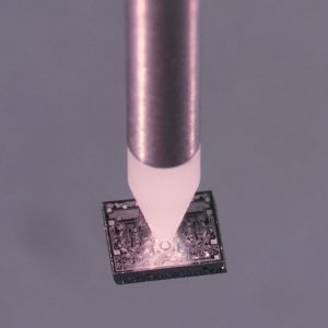
Die Bonding
placing
microchips
placing
microchips
Die bonding or chip bonding is the process step of attaching components to a PCB, wafer, or base plate of an application. First, adhesive or epoxy is applied to the desired location on the application. This can be done by using a dispenser or a stamping tool. The component to be bonded, a so-called “die” or microchip, is then picked with vacuum and placed on the prepared adhesive point. Downforce duration and strength ensures a stable and repeatable result. The entire process is also known as "pick & place" and is usually the last step before wire bonding.
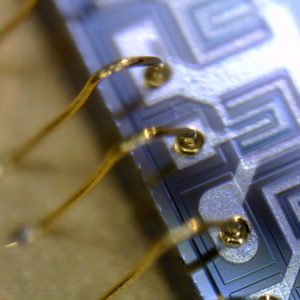
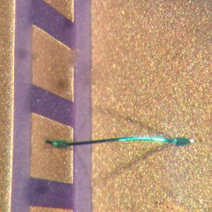
Wedge-Wedge
wedge-bonding
with 25µm gold wire
wedge-bonding
with 25µm gold wire
Ultrasonic Wedge Bonding or US Bonding is used for bonding gold or aluminum wire. For power applications, copper wire can also be used. There are three different kinds of wire bonding: Thin wire bonding or just wire bonding with wires from 17 µm up to 75 µm. Heavy wire bonding with wires from 100 µm up to 500 µm. And ribbon bonding with flat-band ribbons of different sizes.
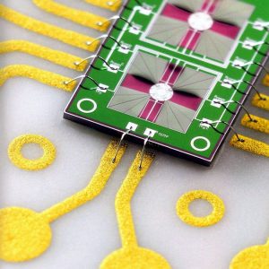
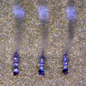
Ball-Wedge
ball-bonding
with 25µm gold wire
ball-bonding
with 25µm gold wire
Thermosonic Ball Wedge Bonding or TS Bonding uses a combination of heat, pressure, and ultrasonic energy to create a weld between a gold, copper or silver ball and the surface of a chip. A gold, copper or silver wire is threaded through a capillary made from ultra-fine ceramics on which tip a high-voltage electric charge is applied to the wire. This melts the wire into a ball, called flame off. With pressure (bond force) and ultrasonic energy the capillary connects this ball now to the surface of the substrate. After that a loop is formed and a second bond applied in the form of a wedge bond, also called stitch bond.
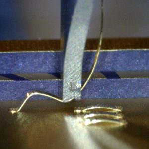
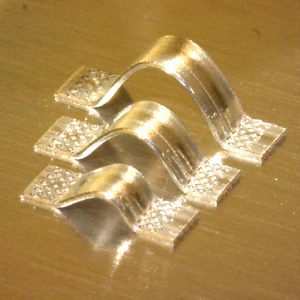
Ribbon
bonding
with ribbon
bonding
with ribbon
Ribbon connections are low in impedance and have a considerable heat dissipation. Due to these characteristics ribbons are frequently used in radio frequency (RF) technology.
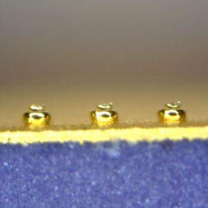
Bumps
bump-bonding
in flip-chip applications
bump-bonding
in flip-chip applications
Bump bonding is used for flip-chip applications: mounting a chip up-side-down directly onto a substrate or second chip. No additional wire is used, and the contact is established solely by beforehand applied bumps. This method is very compact and low in inductance, due to the short conductor lengths. Furthermore, it is possible to stack multiple chips on top of each other.
Heavy Wire
bonding wire
from 100μm to 500μm
bonding wire
from 100μm to 500μm
Heavy wire bonding with wire diameters of 100μm to 500μm is used in power electronics such as used for LEDs, batteries and in the automotive sector.
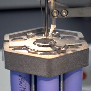
Battery
bonding
battery packs
bonding
battery packs
TPT's HB30 Heavy Wire Bonder with automatic Z- & Y- Axis is ideal for Battery Bonding. The motorized axis allows precise loop repetition.
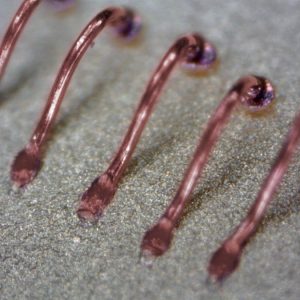
Copper
bonding with
copper wire
bonding with
copper wire
Preparing mass production or facing a special application, it may be necessary to switch from the common materials gold and aluminum to copper. The advantages of copper wire are a cheaper wire price, better electrical conductivity and better thermal conductivity.
Coated
bonding aluminum
coated copper wire
bonding aluminum
coated copper wire
When bonding with copper wire, the copper has to be protected from oxidation by using a special antioxidation gas. This complicates the work process. An alternative could be bonding copper wire with aluminum coating. It can be easily wedge bonded and is well storable.
Insulated
bonding insulated
wires over soldering
bonding insulated
wires over soldering
Insulated wires are short circuit proof due to the full insulation of the wire. Insulated wires are usually soldered. In some cases connecting the wire with a bonder can be a viable alternative.
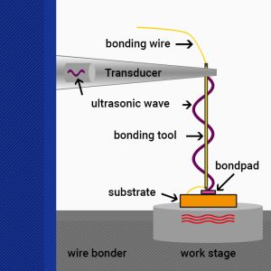
Wire Bonding
Wire Bonding
Technologie
Wire Bonding
Technologie
For decades ultrasonic and thermosonic wire bonding has become one of the most important processes in microelectronic packaging, due to its high flexibility and cost-efficiency. It is used to interconnect all kinds of microelectronic parts like semiconductor devices, chips, LEDs, PCBs, and so on. The process itself uses ultrasonic, pressure, and temperature to weld metal wires to dedicated bonding pads. The intermetallic connection is made without melting the materials, therefore wire bonding is referred to as “cold welding process”. There is a numerous amount of wires and tools available matching all kinds of specific needs. To match the technical needs of the finest IC up to high-power electronics, the wire bonding spectrum reaches from ultra-thin round wires (12 µm diameter) to heavy ribbon wires with cross sections of up to 200x2000 µm2. While wedge-wedge bonding is available for heavy and thin wire bonding, the ball-wedge bonding process is exclusively done with thin wires.
Wire Bonding Techniques
There are two main
methods in wire bonding
Within these two procedures, a distinction is made between different techniques.
Ultrasonic bonding / US bonding
Thermosonic bonding / TS bonding
Thermocompression bonding / TC bonding
The application criteria determine the required wire bonding technology, the corresponding bonding process and the general procedure for wire bonding.
Techniques
There are two main
methods in wire bonding
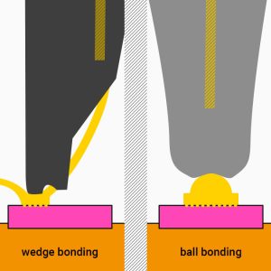
BALL-WEDGE-BONDING („Ball Bonding“) AND WEDGE-WEDGE-BONDING („Wedge Bonding“)
Within these two procedures, a distinction is made between different techniques.
Ultrasonic bonding / US bonding
Thermosonic bonding / TS bonding
Thermocompression bonding / TC bonding
The application criteria determine the required wire bonding technology, the corresponding bonding process and the general procedure for wire bonding.
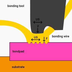
Wedge Bonding Process
welding process for
ultrasonic and thermosonic bonding
First, the wire bonder tool presses the wire onto the substrate and slightly deforms it.
2. Removal of contamination:
The wire oscillates on the metallization by the ultrasound from the piezo crystal in the transducer. The movement breaks up and eliminates minor impurities.
3. Welding of the surface:
Particles of wire and bond pad form a connection. In the end it is stronger than the connection between wire and tool.
Process
welding process for
ultrasonic and thermosonic bonding
1. Approximation of wire and bond pad:
First, the wire bonder tool presses the wire onto the substrate and slightly deforms it.
2. Removal of contamination:
The wire oscillates on the metallization by the ultrasound from the piezo crystal in the transducer. The movement breaks up and eliminates minor impurities.
3. Welding of the surface:
Particles of wire and bond pad form a connection. In the end it is stronger than the connection between wire and tool.
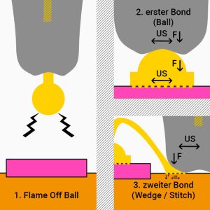
Ball Bonding Process
welding process for
thermocompression bonding
2. An electric flame of (EFO/capacitor discharge) melts the wire. The surface tension of the gold wire forms the melted part into an even ball.
3. This ball is pressed by the capillary’s lower tip/chamfer onto the substrate and welded on.
4. At the second bond, the edge of the capillary/outer radius is pressed onto the wire and deforms the wire with pressure and ultrasonic power (stitch bond).
5. The wire is then torn off and a new gold ball is formed by the EFO.
Process
welding process for
thermocompression bonding
1. Thin gold wire (between 17µm and 50µm Ø) is passed through a wire bonder mounted capillary with a polished tip.
2. An electric flame of (EFO/capacitor discharge) melts the wire. The surface tension of the gold wire forms the melted part into an even ball.
3. This ball is pressed by the capillary’s lower tip/chamfer onto the substrate and welded on.
4. At the second bond, the edge of the capillary/outer radius is pressed onto the wire and deforms the wire with pressure and ultrasonic power (stitch bond).
5. The wire is then torn off and a new gold ball is formed by the EFO.

